 QSFP-DD to QSFP-DD-400G-AOC-25M82FT
 400G QSFP-DD 8 x 50G PAM4 Active Optical Cable, 25m (82ft)
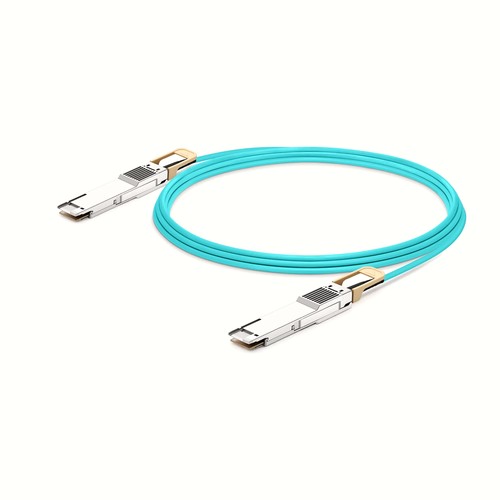
The QSFP-DD to QSFP-DD-400G-AOC-25M82FT cable on this page is the 25m (82ft) version for Generic hosts requiring 400G operation. Its QSFP-DD to QSFP-DD AOC construction reduces the connection to one factory-terminated assembly. Related lengths, brand cross-references and rack-integration notes support a precise high-density deployment.
OEM Part Number: QSFP-DD to QSFP-DD-400G-AOC-25M82FTHT Part Number: QSFP-DD to QSFP-DD-400G-AOC-25M82FT
Product Highlights
- HT-manufactured AOC assembly in 25m (82ft)
- 400G connectivity at 400Gbps
- Interface configuration: QSFP-DD to QSFP-DD
- Fixed length and part number: 25m (82ft), QSFP-DD to QSFP-DD-400G-AOC-25M82FT
- Cable construction: OM4
- Maximum power consumption: 8W Per End
- Minimum bend radius: 30mm
- Operating temperature: 0 to 70°C (32 to 158°F)
Specifications
| HT Part Number | QSFP-DD to QSFP-DD-400G-AOC-25M82FT |
|---|---|
| Manufacturer | HT |
| Form Factor | QSFP-DD to QSFP-DD |
| Max. Data Rate | 400Gbps |
| Cable Length | 25m (82ft) |
| Cable Type | OM4 |
| Wavelength | 850nm |
| Minimum Bend Radius | 30mm |
| Transmitter Type | VSCEL |
| Receiver Type | 850nm PIN |
| Max. Power Consumption | 8W Per End |
| Jacket Material | OFNP |
| CDR (Clock and Data Recovery) | TX & RX Built-in CDR |
| Modulation Format | PAM4 |
| DDM/DOM | Supported |
| Commercial Temperature Range | 0 to 70°C (32 to 158°F) |
| Protocols | IEEE 802.3cd, OIF-CEI-04.0, QSFP-DD MSA,QSFP-DD-CMIS-rev4p0 |
| Inbuilt FEC | No |
| Application | 8x 50G-PAM4 |
Signal and Lane Configuration
The listed modulation format is PAM4. Both host interfaces must be configured for the same aggregate rate and lane arrangement. A connector that fits mechanically does not by itself guarantee that the remote port supports this encoding or breakout mode.
Power and Thermal Planning
The rated power consumption is 8W Per End. Include this load in the host-port power and thermal budget, especially in densely populated switches. Maintain front-panel clearance and do not bundle the cable so tightly that it obstructs airflow around the connectors.
Cable Construction and Routing
This assembly uses OFNP jacket, minimum bend radius 30mm. These mechanical characteristics affect how the cable should be dressed behind the equipment. Avoid sharp edges, excessive ties and repeated tight bends close to the connector boots.
Network and Protocol Considerations
The intended application is 8x 50G-PAM4. Listed interface and protocol references include IEEE 802.3cd, OIF-CEI-04.0, QSFP-DD MSA,QSFP-DD-CMIS-rev4p0. Confirm that the host firmware and port configuration support the same operating mode.
Integrated Optical Assembly
The optical engines and fiber are permanently integrated into this AOC. There are no detachable optical modules to clean or exchange. Handle the complete assembly by its connector housings and cable, and keep both ends matched to the same interface specification.
Length Selection and Installation Planning
The installation review for a 25m (82ft) link should include pathway length, support points, connector access and future maintenance. Route the integrated optical cable and both optical engines before attaching both ends, and avoid dragging it across connector panels. A final inspection should confirm that no latch, boot or jacket section carries unnecessary strain. Within this family, QSFP-DD to QSFP-DD-400G-AOC-20M66FT is shorter at 20m (66ft), while QSFP-DD to QSFP-DD-400G-AOC-30M98FT is the next longer choice at 30m (98ft); comparing those two boundaries helps avoid both tension and unnecessary slack.
Position Within the Length Range
QSFP-DD to QSFP-DD-400G-AOC-25M82FT occupies the middle of this family between QSFP-DD to QSFP-DD-400G-AOC-20M66FT at 20m (66ft) and QSFP-DD to QSFP-DD-400G-AOC-30M98FT at 30m (98ft). It adds 5m over the shorter option for extra routing clearance, while the next longer version adds another 5m. Measure the managed path and choose this version when its reach is sufficient without creating the slack associated with the longer assembly.
High-Density Rack Integration
In a densely populated rack, connector access and airflow are part of the link design. Choose the shortest length that follows the managed path comfortably, avoid tight bundles around the connector housings and preserve room for latch operation. Where power consumption is listed, include every populated interface in the host thermal budget rather than assessing a single cable in isolation. For this assembly, the minimum bend radius is 30mm; the stated power consumption is 8W Per End; the jacket material is OFNP.
Quality Assurance and Packaging
Each assembly receives a visual connector inspection and functional link check before it is coiled and protected. Packaging is selected to avoid compressing the cable into a tight bundle, and optional rack-based labels help maintain an orderly installation when many identical interfaces are populated together. Volume orders can include customer references on the labels and carton list.
Ordering Information
Provide the exact part number, length, quantity and target interface density. For multi-rack projects, list each length separately and identify any preferred carton grouping. Host model and software information can be included for a compatibility review before production or dispatch. Keep QSFP-DD to QSFP-DD-400G-AOC-25M82FT associated with 25m (82ft) throughout the order and receiving record.
Generic Compatibility and Factory Testing
The assembly is evaluated for host recognition and stable link operation, with diagnostics checked where the interface provides them. This approach verifies more than electrical or optical continuity. Exact platform and firmware information remains valuable in high-density deployments because port mode and qualification policy can differ within the same connector family. Where supported by the host, receive activity and diagnostic indications are reviewed together with the established link.
Frequently Asked Questions
Is this an original equipment manufacturer cable?
No. It is manufactured by HT under our own manufacturer identity.
Are separate transceivers or patch leads required?
No. This is one complete direct-attach assembly. The ends are not detachable modules and should not be separated from the cable.
Can excess cable be folded into a compact bundle?
No. Use a supported, bend-safe service loop and observe the listed minimum bend radius. Do not crease the cable or tighten ties around the connector boots.
Will any matching connector operate at the same speed?
Not necessarily. Both hosts must support the stated rate, identification, lane mapping and any required breakout configuration; mechanical compatibility alone is insufficient.
Shipping and Lead Time
Available stock is normally prepared for dispatch within one to three working days, while larger production requirements are scheduled with the order. Delivery can be arranged by courier, air freight or sea freight, and goods may instead be handed to an appointed forwarder or shipped on the customer’s courier account.
